
Generating an emergency signal#
Apply gain control to optimize signal transmission over cable and antenna media
Explain how transmission medium affects signal strength and range
Explain the effect of noise on digital modulation and where noise comes from
Describe letters are sent over a digital channel
Explain how packet-based communication works including destination address and redundancy check
Transmitting an analog signal#
Let us start simple by feeding the signal directly to the SDR.
Tip
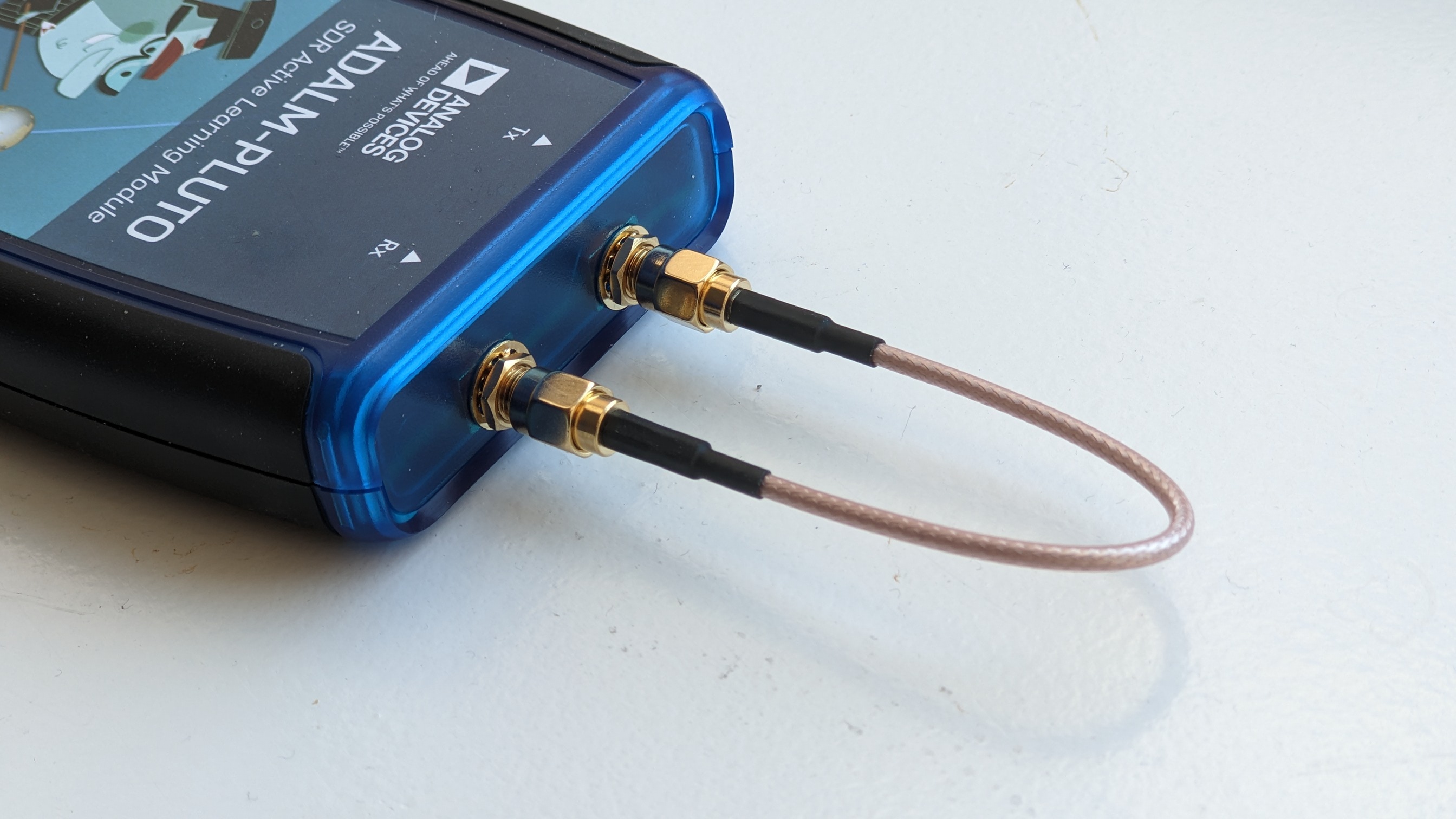
If you are in a class and do not want to avoid interfering other students, use the loopback cable as follows:
Run the following graph with your SDR.

Fig. 4 Flow graph with frequency spectrum and waterfall diagram. gnuradio/transceiver_analog.grc. You also have to download gnuradio/temperature.wav.#
Exercise 9 (Transmitting an analog signal)
We will transmit and receive the signal with our own device.
Connect together the
TxandRxports with a cable.Run the flow graph. Do you hear anything?
Modify
wav_gain,tx_gainandrx_gain. What happens?Optional: Is the RF signal that is transmitted by the antenna an AM signal? For the detailed formula of AM refer to the \(y(t)\) shown here.
Exercise 10 (Transmitting the signal with antennas)
Connect two antennas and run the flow graph.
Do you hear any signal? If not, can you fix this with
wav_gain,tx_gainandrx_gain? If you could fix, why?Optional: Try to create a one-way communication with your neighbor by deactivating one of the tx or rx blocks both on your and your neighbor’s side. Put the devices side by side. Pick the minimum gain values which is sufficient for communication. Now, replace the antenna with a longer one that you can borrow from the professor. What do you observe?
Details of AM is out of the scope of this course. If you are interested, refer to this video by Tall Paul.
Transmitting a digital signal#
Run the following flow graph which encodes random data from 0 to 255 using a modulation technique called BPSK:

Fig. 5 A modulation technique (BPSK): 0 is encoded as -1, 1 is encoded as +1.
CC BY-SA 3.0. By No machine-readable author provided. Splash assumed (based on copyright claims).. Source: Wikimedia Commons#

Fig. 6 Flow graph that transmits receives encoded temperature signals using digital modulation. gnuradio/temperature_modulation_digital.grc.#
Explain the processing chain and what each diagram shows.
Exercise 11 (Noise)
Change the noise. How does noise effect the values drawn on the diagrams?
Packet-based communication#
In computer networking, we typically enclose the data that we want to transmit in a packet. A packet can look like this:

Fig. 7 An Ethernet data packet. The Destination and Source allow the packet to be received by its destination. Payload is the actual content.
Public domain. By Self-made. Source: Wikimedia Commons#
Show an HTTP packet in Wireshark.
The following flow graph:
Generates data with a number of bytes
Generates a signature for the data called CRC (cyclic redundancy check)
Assembles the following in a packet in order:
Header – called access code in the flow graph (4 bytes)
The length of the transmitted data in bytes (two bytes); repeated two times (2 * 2 bytes = 4)
Data
CRC (4 bytes)
Modulates the packet bits
Demodulates and extracts bits again
Searches for the header, if it is found, it extracts the
lengthand readslengthbytes.Checks CRC. If correct, then prints the the content to the terminal.

Fig. 8 Flow graph that represents packet-based communication. gnuradio/packet_based_communication.grc.#
Download and run the flow graph. You should see two time sinks.
Exercise 12 (Packet components)
What could be the advantage of
a header (access code)?
CRC (cyclic redundancy check)?